INDUSTRIAL ELECTRIC FURNACES
- Manufacturing of industrial thermal equipment
- Own design and production facilities
- Modern equipment and machines
ON ELECTRIC FURNACE
Furnaces for calcining welding flux
Purpose and application
Calcining the welding flux produced to remove moisture, which helps to improve the weld.
For calcining the flux, a specialized mine muffle electric furnace with a loading and dosed unloading mechanism is proposed. Material loading is done from above, and unloading from below, which is convenient for in-line production. Serially, as a loading mechanism, it is offered skip lift. Unloading is carried out into the workshop container by turning the gate valve. The volume of the permissible furnace load is selected in proportion to the productivity of the welding production. For heat treatment, it is possible to set, almost any, heating intensity, holding time and cooling rate.
Furnace device
Structurally, furnaces for flux calcination are of shaft type with a sealed muffle. Heating chamber formed inside a steel frame, in the form of a hexagonal vertical chamber. The frame has an opening in the bottom to accommodate a pouring funnel. From above, the frame overlaps with a support sheet for fixing the muffle. The sheet has a slot for the outlet of the vapor discharge tube.

From the inside, the frame is lined with fibrous thermal insulation with combs for fixing the heaters. Under the furnace, it is lined with dense and heat-insulating bricks with fibrous layers. Fiber insulation minimizes heat storage and is very economical under cyclic loads such as heating and cooling.
Heaters are passed through ceramic tubes, which are fixed at the edges in combs and do not touch the thermal insulation. Are the heaters made of Superfechral alloy wire? increased cross-section, for long holding cycles at high temperatures by reducing the applied voltage. As a rule, such furnaces are made with one adjustable zone and the switching of the heaters into a star..
As an option, it is possible to install additional thermocouples to meet all the requirements of the RD manual 5.90.2346-85.
The flux is directly calcined in sealed muffle. The muffle is connected from below to a rotary slide, which is located in the heating chamber, and below it with a pouring funnel. The muffle has a support flange on top, which also serves for sealing with a cover. At the level above the backfill and below the cover, a pipe for removing vapors and fumes is welded. The tube is led out into a cold area to be connected to an exhaust ventilation. A protruding heat-resistant cord seal is fixed around the perimeter of the flange.
Oven cover localizes the temperature field in the heating chamber zone and provides gas seal of the muffle space. The cover consists of a welded hexagonal box. Fibrous thermal insulation is laid inside the box, and several layers of ball screws, commensurate with the diameter of the muffle, are attached with studs from below. Downwardly protruding plates protect the high-temperature steel disc.
The lifting and rolling back of the cover is mechanized. The cover is suspended by chains on a special retractable frame. First, the lid rises above the muffle, and then rolls to the side, freeing the loading opening. Lifting is carried out by a geared motor along two vertical guides until the limit switch is triggered. After lifting, the retractable frame, together with the cover, moves along the rail guides in the direction opposite to the loading device.
The control system of the furnace and the loading mechanism, as well as the power section, is mounted in the control cabinet, which is connected to the consumers by electric wires. The front side of the cabinet shows the layout of the main devices and control buttons. As an option, a wireless control panel for the drives is offered. The location of the lid and skip, at a particular moment, is indicated by the position indicator lights.
On the front panel, there is a thermostat of the "Termodat 16E6 / F" brand, with a USB connector "for temperature control. Provides digital indicators of voltage and current, temperature recording device.
Heating regulation is performed by thyristor units with PWM control function. The system provides heating for calcination, with the necessary signaling and blocking of unacceptable (emergency) situations.
Possible executions
Electric furnaces for flux calcination can be used for calcining other materials similar in density and flowability, for example, sand.
EPSF electric furnaces can be manufactured with a maximum heating temperature up to 1000 ° C.
If necessary, it is possible to fully automate the calcination process.
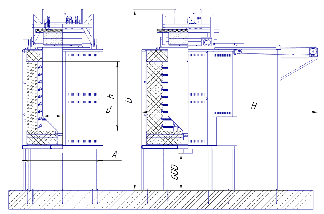
Main technical characteristics of electric flux calcining furnaces
| Designation | Working dimensions (d × h), mm. | Dimensions (A × B × H), mm | Power, kWt | Furnace weight, kg | Loading weight |
|---|---|---|---|---|---|
| ЭПСФ-60/1000М | 550×1000 | 1400×3800×2800 | 15 | 1600 | 140 |
| ЭПСФ-80/1000М | 700×1200 | 1600×4380×3280 | 20 | 2200 | 200 |
| ЭПСФ-100/1000М | 900×1400 | 1900×5000×3700 | 75 | 1650 | 250 |
- «М» in the designation indicates the mechanization of loading.
- Overall dimensions are indicated without taking into account the loading mechanism.
- The height of the flux pouring out of the furnace will be at least 600mm.
View design sketch
Electric furnaces for gumboil calcination can be equipped with skip, auger or belt feeders, or lifters. The furnace design meets the requirements of RD 5.90.2346-85. The thermostat can operate in the mode of maintaining the set temperature or along the heating path. It is possible to carry out installation supervision and commissioning works.
(the territory of OJSC "Ural plant RTI")